EF-4.3 – KINEMATICS – DRIVE SYSTEMS
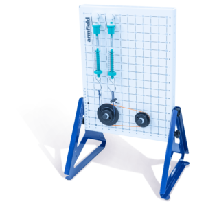
The EF-4.3 Drive Systems experiments kit introduces students to various types of belt, chain, and shaft drive systems.
2 trays supplied with EF-4.3
DESCRIPTION
The Engineering Fundamentals range enables students to gain an understanding of the principles of engineering by the process of learning via experimentation.
The EF-4.3 Drive Systems experiments kit introduces students to various types of belt, chain, and shaft drive systems.
Belt and chain drive experiments are included to demonstrate the characteristics of different belt and chain systems with multiple velocity ratios. The efficiency can be calculated for varying loads for both the different velocity ratios and the different belt and chain systems allowing comparisons between the different systems to be observed. Experiments are also included to demonstrate the effect of belt tension and the effect of pulley lap.
Experiments in universal couplings define how they should be set up to ensure that the rotational velocity from the input is seen at the output. The angle of each universal joint and the orientation relative to each other will be tested to see which setup will give uniform angular transmission.