2/B, Firdous Masjid Market, Mirpur 2, Dhaka 1216
+88-01633442266
Saturday-Friday: 09:00 AM - 06:00 PM

TH3 – SATURATION PRESSURE

The Armfield Saturation Pressure Apparatus has been designed to introduce students to how the temperature of water behaves at its boiling point with variation in the absolute pressure.

The TH3 offers all the features of a Marcet Boiler and adds the capability of determining the quality of wet steam, thus enhancing the understanding of the underlying thermodynamic principle.

DESCRIPTION

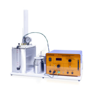
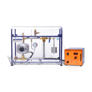
A bench top unit designed to introduce students to the characteristics of saturated water vapour.

The apparatus is equivalent to a Marcet Boiler, with an additional throttling calorimeter and a pipe loop, which enables saturated steam to be returned to the base of the boiler as condensate.

Pure water in the boiler is heated to its boiling point using a pair of cartridge heaters with variable power control. A sight glass on the front of the boiler enables the internal processes to be observed, namely boiling patterns at the surface of the water, and also permits the water level in the boiler to be monitored.

Saturated steam leaving the top of the boiler passes around the pipe loop before condensing and returning to the base of the boiler for reheating. The operating range of the boiler and loop is 0 – 7 bar. The top limb of the pipe loop incorporates a Platinum Resistance Thermometer (PRT), temperature sensor and an electronic pressure sensor to measure the properties of the saturated steam. A filling point on the top limb enables the loop to be filled with pure water and permits all air to be vented safely before sealing the loop for pressurised measurements.

A vapour offtake, with isolating valve, enables steam from within the loop to be passed through a throttling calorimeter, the purpose of which is to demonstrate how the dryness fraction of the saturated steam in the
loop can be determined.

The steam expands to atmospheric pressure as it is throttled and a second PRT temperature sensor measures the temperature of the steam following expansion.

The apparatus is designed for safe operation with a pressure relief valve set to operate if the pressure rises above the working pressure and a Bourdon gauge that remains operational when power is disconnected from the electrical console.

All power supplies, signal conditioning, circuitry etc. are contained in an electrical console with appropriate current protection devices and an RCD for operator protection. Readings from the sensors are displayed on a common digital meter with selector switch and all corresponding signals are routed to an I/O port for connection to a PC using an optional parallel interface/educational software package.

TH1 – TEMPERATURE MEASUREMENT AND CALIBRATION

The Armfield Temperature Measurement And Calibration Unit is designed to introduce students to temperature and how different techniques can be employed to measure this variable.

DESCRIPTION

A bench top unit designed to introduce students to temperature, temperature scales and commonly available devices to measure temperature.

The equipment comprises a hypsometer/hot water bath and ice flask to generate accurate fixed points (the condensation point and triple point of water) and variable temperatures.

Temperature sensors with different thermometric principles and characteristics are supplied. An accurate platinum resistance thermometer (PT100) with five point NAMAS calibration certificate and temperature indicated directly in °C, is included for reference.

The temperature of the condensing water vapour in the hypsometer can be determined accurately using the software or tables in the manual, providing knowledge of the barometric pressure is known. The water level is simply raised to change the hypsometer into a variable temperature water bath.

The unit is designed for safe operation with insulation surrounding the vessel and a protected steam vent. A radiation shield surrounds the sensors to be calibrated to minimise measurement errors. A common carrier enables all sensors to be transferred simultaneously from ice flask to the hypsometer/water bath.

All thermometric properties and temperatures measured are displayed on a digital meter with selector switch.

All important electronic sensors used on the unit provide outputs for data logging and analysis. The data logger, provided with the unit, interfaces between the unit and the user’s computer using a USB port.

The optional educational software package enables data recording, graph plotting and provides full instructions for setting up equipment and performing the experiments.

All related theory and help texts are provided. The software requires a computer (not supplied) running Windows 7 or later with a USB port.

The following sensors/signal conditioning circuits are included:

  • Accurate reference PRT with linearised output in °C
  • Industrial PRT with a bridge circuit to measure the resistance in Ohms. Higher current can be passed through the sensor to show the effect of self-heating
  • Type-K thermocouple using a precision preamplifier to measure the thermoelectric voltage with cold junction compensation or a second thermocouple in ice as required
  • Additional thermocouples enable errors due to response and conduction to be demonstrated. An additional conditioning circuit with user adjustable zero and span controls enables the output to be displayed as a direct reading thermometer calibrated in °C
  • Thermistor with constant current through the sensor to measure the resistance in Ohms
  • In addition to the thermoelectric sensors a liquid in glass and vapour pressure thermometer are also supplied

C30 – COMPUTER CONTROLLED WIND TUNNEL

The C30 – Computer Controlled Wind Tunnel enables the user to carry out advanced studies in the Aerodynamics fields.

These include boundary layer experiments, flow visualisation, pressure distribution, study of turbulence and offer the possibility of developing self-design aerodynamics profiles to be tested.

DESCRIPTION

The C30 – Computer Controlled Wind Tunnel enables the user to carry out advanced studies in the Aerodynamics fields including boundary layer experiments, flow visualisation, pressure distribution, study of turbulence and offering the possibility of developing self-design aerodynamics profiles to be tested.

The wind tunnel comprises outstanding features such as computer control, remote operation, datalogging and diagrams plotting in real time.

The system also benefits from clear visualisation of every model under test due to the architecture of the working section in transparent material and the compact design of all components.

C15 – COMPUTER CONTROLLED SUBSONIC WIND TUNNEL

A compact benchtop wind tunnel, with visible working section.

A wide range of accessories and instrumentation options are available, allowing a comprehensive study of Subsonic Aerodynamics and Fluid Mechanics.

DESCRIPTION

The C15-10 is a computer controlled compact wind tunnel designed for benchtop operation. Air is drawn through the working section by a variable speed fan at the discharge end of the tunnel providing up to 34m/s air velocity.

A honeycomb flow straightener is incorporated at the inlet, and a 9:4:1 contraction ratio which ensures an uniform airflow through the working section.

The working section is fabricated from clear acrylic to provide optimum visibility of the models, and appropriate model connection points are included in the side wall and roof of the working section to provide ease of use.

The wind tunnel is supplied as standard with an in-depth software interface providing control of the fan speed and additionally display important parameters such as static pressure and air velocity.

The Armfield C15-10 can be optionally supplied with two variants of manometry banks, a 13 tube water manometer used to simultaneously display differential pressure or a sixteen channel electronic manometer allowing direct integration into the supplied software.

The wind tunnel can be supplied with a range of optional accessories including drag bodies, lift bodies, pressure distribution, boundary layers studies and measuring instruments.

The optional models are mounted through a circular hatch using quick release clamps (120mm diameter). The placement of the optional models has been designed to minimise the disturbance to air flow and reduction in flow rate, whilst incorporating an angular scale allowing the model to be manually rotated to known angles.

The working section incorporates an innovative technique for flow visualisation around any of the optional models avoiding the need for either smoke or dry ice. A lightweight twine follows the flow contour around the model and shows if and where boundary layer separation (breakaway) occurs.

C6-MKII-10 – FLUID FRICTION MEASUREMENTS

The Armfield C6-MKII-10 Fluid Friction Measurements unit provides facilities for the detailed study of fluid friction head losses, which occur when an incompressible fluid flows through pipes, fittings and flow metering devices.

Pipe friction is one of the classic laboratory experiments and has always found a place in the practical teaching of fluid mechanics.

DESCRIPTION

The Armfield C6-MKII-10 Fluid Friction Measurements unit provides facilities for the detailed study of fluid friction head losses, which occur when an incompressible fluid flows through pipes, fittings and flow metering devices.

Pipe friction is one of the classic laboratory experiments and has always found a place in the practical teaching of fluid mechanics.

With this unit, friction head losses in straight pipes of very different sizes can be investigated over a range of Reynolds’ numbers from10³ to nearly 10⁵. This covers the laminar, transitional and turbulent flow regimes in smooth pipes.

In addition an artificially roughened pipe is supplied, which at the higher Reynolds’ numbers shows a clear departure from the typical smooth bore pipe characteristics.

In addition to the equipment for the study of losses in straight pipes, a wide range of accessories are included such as pipe fittings and control valves, a Venturi tube, an orifice plate assembly and a Pitot tube.

An arrangement of six pipes provides facilities for testing the following:

  • Four smooth bore pipes of different diameters
  • Artificially roughened pipe
  • 90° bends (large & small radii)
  • 90° elbow
  • 90° mitre
  • 45° elbow
  • 45°Y
  • 90°T
  • Sudden enlargement
  • Sudden contraction
  • Gate valve
  • Globe valve
  • Ball valve
  • Inline strainer
  • Perspex venturi
  • Perspex orifice meter
  • Perspex pipe section with a pitot tube & static tapping 

Short samples of each size test pipe are provided loose so that the students can measure the exact diameter and determine the nature of the internal finish.

The ratio of the pipe diameter to the distance of the pressure tappings from the ends of each pipe has been selected to minimise end and entry effects. A system of isolating valves is provided whereby the pipe to be tested can be selected without disconnecting or draining the system. This arrangement enables tests to be conducted on parallel pipe configurations.

An optional floor-standing Hydraulics Bench incorporates a sump tank and volumetric flow measurement facility. Rapid and accurate flow measurement is possible over the full working range of the apparatus.

The level rise in the measuring tank is determined by an independent sight gauge. A 250ml capacity glass measuring cylinder is supplied for measuring the flow rate under laminar conditions (very low flows).

Each pressure tapping is fitted with a quick action self-sealing connection. Probe attachments with an adequate quantity of translucent polythene tubing are provided so that any pair of pressure tappings can be rapidly connected.

All the test pipes and fixed interconnecting pipes are fabricated in stainless steel.

Technical details for test pipes:

Diameter:
1. 19.1mm OD x 17.2mm ID
2. 12.7mm OD x 10.9mm ID
3. 9.5mm OD x 7.7mm ID
4. 6.4mm OD x 4.5mm ID
5. 19.1mm OD x 15.2mm ID (Roughened)

Distance between tappings: 1m

Number of tapping points: 38

Constant Head Permeameter Set

Used to determine the permeability of granular, gravel and sandy soils.

The specimen is formed in an acrylic permeability cell and water is passed through it from a constant level tank.

The permeability cell has pressure points at different levels which are connected to the manometer tubes fixed on a stand with graduated scale.

Two Constant Head Permeability Cells are available; ∅ 75 mm and ∅ 114 mm.

Constant head permeability cell ∅ 75 mm, with three pressure take-off points. Formed by an acrylic Plexiglas body held between two aluminum anodized end plates. Supplied with 2 pieces Perforated plates and 2 pieces No.100 screen.

Constant head permeability cell ∅ 114 mm, with six pressure take-off points and an additional six blanked-off pressure points. Formed by an acrylic Plexiglas body held between two aluminum anodized end plates. Supplied with 2 pieces Perforated plates and 2 pieces No.100 screen.

The Stand, comprising 3 pieces ∅ 6 mm x 1 m long Manometer Tubes of constant bore, graduated scale, Rubber Tube and Connectors.

Constant Level Tank, made from acrylic Plexiglas, wall mounting, is used to provide constant water level in the manometer tubes. The inlet, outlet and overflow pipes can be adjusted for height within the tank.

HR-S5800 Model, Supplied complete with Ø 75 mm Constant Head Permeability Cell, Stand with 3 pieces Manometer Tubes, Constant Level Tank, Rubber Tube and 1 m Steel Ruler.

HR-S5810 Model, Supplied complete with ∅ 114 mm Constant Head Permeability Cell, Stand with 3 pieces Manometer Tubes, Constant Level Tank, Rubber Tube and 1 m Steel Ruler.

Relative Density Test

Relative density relates the dry density of cohesionless soil to the maximum and minimum densities. The degree of compaction of cohesionless soil can be stated in terms of relative density.

This method, in the EN standard, covers the determination of the maximum dry density and water content of cohesionless materials when compacted using a vibrating table. Materials for which this method is applicable may contain up to 12% by mass fines (<0.063 mm). The maximum particle size of the materials to be tested is 80 mm. This method applies to mixtures to be used in road construction.

The ASTM, also specify that it is used for the determination of the relative density of cohesionless soil for which impact compaction will not produce a well-defined moisture-density relationship curve and where the maximum density of impact method will generally be less than by vibratory method.

The two versions: HR-S7500 Conforming to EN and HR-S7505 Conforming to ASTM are practical identical except for the 0.1 cu.ft. mould.

HR-S7500 Relative Density Test Set Supplied complete with 762×762 mm Vibrating Table (3600 rpm) which adjustable vibration magnitude, 14200 cm³ 0,5 cu.ft. Relative Density Mould Set (Mould, Circular surcharge weight with handle, Surcharge base plate with handle and detachable guide sleeve with clamp assembly) and Relative Density Gauge Set.

HR-S7505 Relative Density Test Set Supplied complete with 762×762 mm Vibrating Table (3600 rpm) which adjustable vibration magnitude, 0,1 cu.ft. and 0,5 cu.ft. Relative Density Mould Set (Mould, Circular surcharge weight with handle, Surcharge base plate with handle and detachable guide sleeve with clamp assembly) and Relative Density Gauge Set.

Relative Density Gauge Set is supplied with Analog displacement dial gauge (50 x 0.01 mm division, 0-100 scale) with holder and Metal calibration bar.

Relative Density Pouring Funnel Set is required for loose placement of 9.5mm and finer granular soils in the Mould Set. The Funnel Set includes two Ø152 x 305 mm metal cylinders, each with funnel and 152 mm long delivery spout attached to one end. Spouts are 25.4 mm and Ø 12.7mm. The pouring devices are mandatory according to ASTM D4253 and should be ordered separately.

Balloon Density Apparatus

Balloon Density Apparatus is used to determine the in-situ density of compacted or firmly bonded soils.

The HR-S7700 consists of a graduated cylinder 1596 ml capacity, housed inside an aluminium guard, a reversible rubber aspirator pump and a density plate 9” square. The principle of operation is similar to the sand replacement but the hole is filled by a rubber balloon where water is pumped. The amount of water can be easily determined by the graduation of the cylinder. Rubber balloons should be ordered separately.

The HR-S7705 is 3000 ml capacity. A metal cylinder is filled with water which is then pumped into a rubber membrane mounted on the base of the cylinder. The water pressure is controlled by a pressure gauge and the volume of the balloon is measured on the graduated piston stem. Rubber balloons should be ordered separately.

Standard Sand

Standard Sand for density tests has two alternatives;
  • passing 600 micronandretained on 300 micron.
  • passing No. 16 (1,18 mm) andretained on No.30 (600 mikron).

Sand Replacement Apparatus

Used to determine the in-situ density of fine grained compacted soil.

Complete set consists of Sand Pouring Cylinder, Metal Tray with Centre Hole and Calibration Container.

The Sand Pouring Cylinder with shutter made of cast aluminum and accurately machined, The Calibration Container and Metal Tray are made of plated sheet steel.

The test set is available in three different sizes.