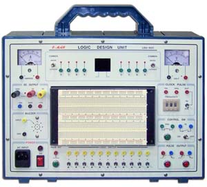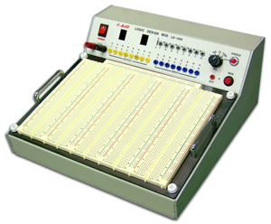
Logic Design BOX, LD-1000
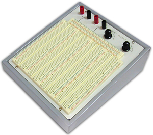
1. Mount the large breadboard board.
2. The breadboard board is easy to attach and detach.
3. Two FND indicators capable of expressing hexadecimal numbers are installed. 4. The power of the DC power supply is sufficient with 5V, 3A. 5. 1㎐, 100㎐, 1㎑, 100㎑ waveforms can be selectively output by the square wave generator. 6. In case of overcurrent output, the piezo operates to warn that it is in an overload state.
1) DC power supply: 5V,3A overload protection circuit and alarm output (piezo)
2) 8bit logic monitor LED (H: on, L: off)
3) BCD DISPLAY: 2-Digit (Hexadecimal number indicator)
0 1 2 3 4 5 6 7 8 9 ABCDEF
0 1 2 3 4 5 6 7 8 9 10 11 12 13 14 15 16 4) Logic supply switch: 8-Toggle SW 5) Logic supply indicator: 8-LED indicator 6) Square wave output: 1 ㎐, 100㎐, 1㎑, 100㎑ selectable output by selector switch 7) SINGLE pulse output 8) RUN switch : square wave output control 9) Bread board : Socket Tie-Point — 3150point Bus Tie-Point — 700point 10) Input Power: AC 220[V],50/60[㎐] 11) Dimension: 130(H) × 280(W) × 280(D)㎜ 12) Accessories ① User Manual : 1EA ② Experiment jump wire : 1 set