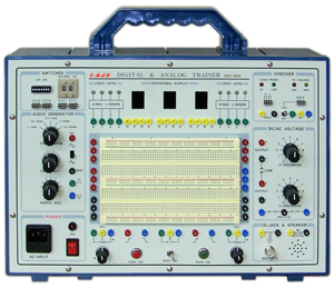
1. Testing and designing of various transistor circuits and OP amp circuits possible
2. Basic operation experiments and circuit designing of various electronic circuits possible
3. Various practical exercises possible without soldering as they are interconnected on the Bread Board
4 Logic Level is displayed by 8 two-color LEDs.
1) Power supply
① POSITIVE DC variable power: DC 3V ∼ 20V 0.5A
② NEGATIVE DC variable power: DC 3V ∼ 20V 0.5A
③ DC fixed power: DC 5V 1.0A
④ DC fixed power: DC ± 12V 0.5A
⑤ AC fixed Power : AC 15V Onion 0.1A
2) Oscillating part
① Sine wave : 1㎐∼100㎑ 5 range
② Triangle wave : 1㎐∼100㎑ 5 range
③ Square wave : 1㎐∼100㎑ 5 range, pulse width variable
3) Logic indicator
① H(=RED) and L(=GREEN) indicator by 2COLOR LED — 8
* LED off in FLOATING status
② H(=RED) and L(=GREEN) indicator by logic PROBE LED
* THRESHOLD voltage : 1V
4) HEXADECIMAL DISPLAY : 3set
8,4,2,1 binary input is decoded and displayed from 0 to 9 and A to F by 7 segment indicator
5) Logic input
① 8421 binary output by BCD switch Thumb Wheel Decimal switch — 2 sets
② Binary DATA Binary input by DIP switch of switch 8 ③ Positive pulse and negative pulse output as passive pulse without logic switch chattering– 2 sets 6) Circuit elements ① Variable resistor: 1 kΩ, 100 kΩ — 1 each ② Speaker : 8Ω/0.3W — 1 pc ③ SPDT switch : 3 position settable — 1 pc ④ BNC I/O conversion jack — 1 pc 7) TR Check NPN PNP TYPE Classification and Transistor EBC CHECK available 8 ) Breadboard Socket Tie-Point : 1260point Bus Tie-Point : 300point 9) Input power 220V, 50/60 ㎐

